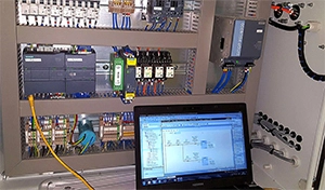

Integrating a OUKE series PLC with a variable frequency drive (VFD) and human-machine interface (HMI) is a common task in industrial automation. While the concept is simple, getting all three components to work together smoothly requires careful planning, correct wiring, and thoughtful programming. This article shares practical steps based on real-world experience to help engineers build a reliable control system.
The OUKE series is well-known in small machine automation. It’s compact, cost-effective, and supports essential functions like high-speed counting, pulse output, and basic communication via RS-232 or RS-485. Many OEMs use it because it’s easy to integrate into various applications — from conveyors to packaging equipment.
In this setup:
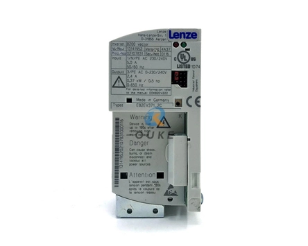
● The VFD controls motor speed and direction. It helps save energy and reduce mechanical wear.
● The HMI gives operators a simple interface to start/stop the motor, adjust speed, and check for faults.
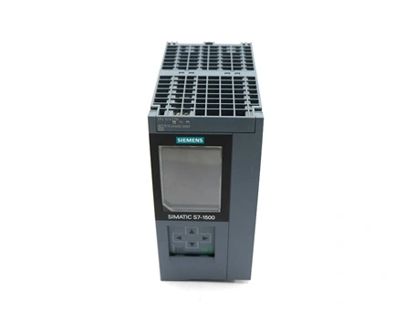
The PLC acts as the brain, handling logic, while the VFD and HMI handle motor control and user interaction.
A typical connection looks like this:
● PLC to VFD: Use RS-485 for communication (usually Modbus RTU). The PLC sends commands, and the VFD replies with status info.
● PLC to HMI: Often RS-232 or RS-485, depending on your hardware. Make sure the HMI driver matches your FX PLC model.
● I/O signals: Hardwired connections can include start/stop signals, fault feedback, and optional speed reference signals if analog control is used.
Tip: Double-check grounding and shield your communication cables to reduce noise issues.
Set the VFD to accept remote commands. Key parameters to check:
● Communication settings: address, baud rate, parity, stop bits
● Frequency limits: minimum and maximum frequency
● Protection: enable features like overload and stall prevention
Your ladder logic will need to:
● Respond to HMI inputs (start, stop, speed setpoint)
● Send appropriate run/stop and direction signals to the VFD
● Monitor VFD feedback (running status, fault alarms)
Keep the logic simple at first, then add layers like interlocks, error handling, or soft start features as needed.
Design clean screens that show:
● Motor status (running, stopped, faulted)
● Speed setpoint
● Basic fault codes or warnings
Avoid cluttering the screen with unnecessary data. The goal is to make operation easy for the end user.
Here are some lessons learned from real installations:
● Test locally first: Run the motor from the VFD keypad to confirm hardware is working before integrating the PLC.
● Match comms settings: Many communication errors are due to mismatched baud rates or parity bits.
● Check termination resistors: On RS-485 networks, proper termination helps prevent data errors.
● Log and clear faults: Make sure your PLC and HMI handle fault conditions clearly so operators know what to do.
Combining an FX PLC with a VFD and HMI gives you flexible, precise motor control for a wide range of machines. By planning carefully, wiring correctly, and keeping the logic clean, you can build a system that’s both reliable and easy to maintain.
If you need help with parts selection, programming, or sourcing hard-to-find Mitsubishi components, OK Automation offers fast delivery and engineering support for small and medium enterprises worldwide.
 English
 日本語
日本語 한국어
한국어 français
 Deutsch
 Español
 italiano
 русский
 العربية
 Türkçe
 Jawa
Jawa